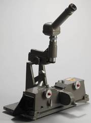
Der "Magnetband-Kleber" von SMITH aus Ala Loma etwa 1958
In USA hatten die Sender (die Radio Stationen) beim Ausprobieren des Videorecorders 2 Jahre Vorlauf gegenüber unseren westdeutschen Sendeanstalten. Dort wurden die ersten Ampex Videorecorder Anfang bis Mitte 1956 ausgeliefert und dort wurde auch sofort mit Ergänzungen und Nachbesserungen aufgewartet. Das Thema mit dem "Schneiden" (cutten) und "Kleben" (splicen) war essentiell wichtig. Ampex wollte natürlich gleich mal eine zweite Videomaschine für 100.000 Dollar verkaufen, doch das war selbst in den "reichen" USA manchem Chef zu teuer. Eine "billigere" Lösung mußte her, abgeguckt von der Tontechnik mit den Magnetophonen. Das war der "MAGNETIC TAPE SPLICER". Daß es bei uns in Germany wenige Jahre später recht komfortable und vor allem verbesserte 2" Schnittmaschinen gab, hatte sich über die Broadcast-Messe in Montreux in den USA erst viel später rumgesprochen.
.
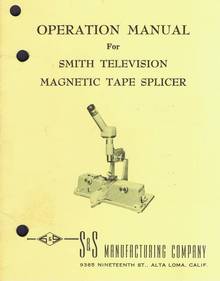
The SMITH SMITH TELEVISION MAGNETIC TAPE SPLICER
S & S MANUFACTURING COMPANY
9385 Nineteenth Street - ALTA LOMA, CALIFORNIA
The Smith Television Tape Splicer was designed and built for those who desire the finest in splicing equipment for the editing of television tape.
This splicer has been used by some of the leading studios for over a year to work out all the problems connected with precision splicing. During that time it was used on hundreds of shows, including many syndicated programs for use throughout the country.
After this long test period, we are happy and proud to offer the Smith Television Tape Splicer to those who wish to do precision splicing of videotape.
.
- Anmerkung : Die Firma Smith & Smith MANUFACTURING COMPANY scheint sich bereits in 1970 "verabschiedet" zu haben, in USA nichts Ungewöhnliches.
.
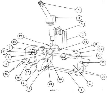
LIST OF PARTS (with refrence to the picture)
- 1. Base Plate
- 2. Optic Stanchion
- 3. Horizontal Optic Movement
- 4. Davidson Micro 40 Graduated Microscope
- 5. Focussing Eyepiece
- 6. Splicer Body
- 7. Left Hold-down Door
- 8. Right Hold-down Door
- 9. Left Tape Advance Knob
- 10. Right Tape Advance Knob
- 11. Left Door Lock Release
- 12. Right Door Lock Release
- 13. Left Tape Lock Knob
- 14. Right Tape Lock Knob
- 15. Light Assembly
- 16. Light Switch
- 17. Tape Raise Lever
- 18. Saddlebar
- 19. Tape Shear
- 20. Splicing Tape Hold-down
- 21. Splicing Tape Magazine
- 22. Saddlebar Vertical Lock
- 23. Saddlebar Horizontal Lock
- 24. Trimming Block (Not Shown)
- 25. Trimming Knife (Not Shown)
- 26. 6 Splicer Body Adjustment Jackscrews
.
FUNCTION OF PARTS
.
- 1. The base plate is the unit upon which the optics and the splicer are securely mounted. The base plate also contains six adjustment jackscrews at the four bottom corners of the splicer body which enables the splicer to be aligned to the optics.
- 2. The optic stanchion is a demountable portion of the base plate which forms a rigid support for the optics.
- 3. The horizontal optic movement is used to align and to check alignment of the lower cutting edge of the tape shear.
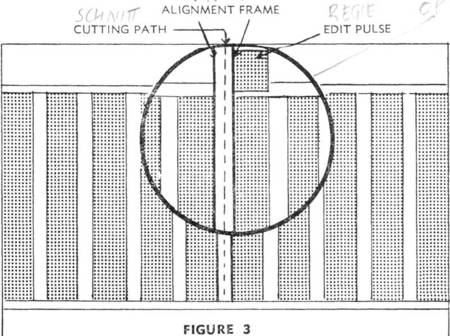
- 4. The Davidson "Micro 40" precision microscope contains an especially designed retical with intervals which match the recorded information lines on TV magnetic tape. The two long vertical lines are known as the "alignment frame".
- 5. The focussing eyepiece has been especially designed for easy focussing for individual operators.
- 6. The splicer body is the unit which all remaining parts (except No. 24, No. 25, and No. 26) are attached. It also contains a 1/8" deep x 2" wide longitudinal tape guide over which the tape hold-down doors are hinged.
- 7. The left tape hold-down door is located on the top lefthand side of the splicer body and is used to hold the tape being spliced secure in the tape guide.
- 8. The right tape hold-down door is located on the top right hand side of the splicer body and is used to hold the tape being spliced secure in the tape guide.
- 9. The left tape advance knob is located on the front face of the left tape hold-dowm door. It is used to obtain proper longitudinal alignment of the tape before cutting.
- 10. The right tape advance knob is located on the right door and is used for the same purpose as the left knob. The rotation of the tape advance knobs, through a Vernier mechanical movement actuates the rubber drive wheel located on the under side of the tape hold-down doors. The rubber wheels contact the tape and their movement shifts the tape in the desired direction longitudinally.
.
- 11-12. The door lock release knobs are, respectively, red knobs located in the center of the tape advance knobs. By pressing these knobs, the locks are released and the doors may be raised. It is also necessary to press these knobs to close and lock the doors. This prevents the doors from being closed accidentally for long periods of time, thus causing a temporary flat spot to be formed on the precision ground neoprene tape advance roller.
- 13-14. The tape locks are two knurled knobs found on the tops of the tape hold-down doors. When these knobs are tightened until they bottom, a neoprene-covered pressure foot is forced down which, in turn, holds the tape securely in place while the splice is being made.
- 15. The light assembly is hinged to the top of the left-hand tape hold-down door and may be swung into position to light the splicing area. After the cut is made, it must be swung back to the "rest" position while the splice is being made.
- 16. The light switch is of the pressure type and is found on the front of the splicer body.
- 17. The tape raise lever is located in the lower left midsection of the splicer body. By turning the lever 90 degrees either left or right, two vertical pins are actuated which lift the cut ends of the tape while the splicing tape is slid into position to make the splice.
- 18. The saddlebar is a bar which slides through the ways in the splicer body at right angles to the tape guide. It carries the knife into position for cutting and the splicing tape into position for the splice.
- 19. The tape shear is mounted on the back end of the saddlebar and is made of special alloy, hardened and precision ground, with spring-loaded take-ups to assure perfect alignment.
CAUTION: At no time should anyone attempt to sharpen the shear.
.
- 20. The splicing tape hold-down consists of two spring-loaded fingers which are used to hold the splicing tape securely in position while the splice is being made.
- 21. The splicing tape magazine is located on the front end of the saddlebar and contains a spring-loaded spool which holds the roll of splicing tape.
- 22. The saddlebar vertical lock is found on the extreme front end of the splicing tape magazine. Its purpose is to lock the saddlebar vertically in either the extreme forward or extreme rear positions. In the vertical position it is unlocked. To lock, move gently to the right until it is seated.
CAUTION: Only enough pressure should be applied to prevent the saddlebar from moving during cutting or splicing operations. - 23. The saddlebar horizontal lock is a round knurled knob located on the extreme right end of the splicer body. Its fvmetion is to force tine saddlebai- against the extreme left side of the saddle, thus causing the cutter blade to return to the same position each time it is locked in place.
- 24. The trimming block is a precisely milled block that is inserted in the tape guide between the hold-down doors. It is used as a guide for trimming off the excess splicing tape after the splice is completed.
- 25. The trimming knife is a keen-edged knife with a rubber roller on one end. The roller is used to apply pressure in order to obtain a firm bond between the splicing tape and the magnetic tape. The knife is used in the trimming operation. The tool is kept in the holder provided on the top of the trimming block when not in use.
- 26. The splicer body adjustment jackscrews are located in the baseplate at the bottom four corners of the splicer body. They serve two purposes: (1) through their use the splicer body may either be rotated on the base plate or moved from right to left; (2) when adjustment is finished and these screws are tight, they hold the splicer body in place.
.
CHECKING PROCEDURE
The Smith Television Tape Splicer has been thoroughly checked and tested at the factory and found to be well within splicing limits. However, in shipping some of the adjustments may have changed due to careless handling and the machine should be re-aligned before using.
Checking should be done in the following order:
- 1. Plug in the AC cord in any 110 volt socket.
- 2. Turn on the light.
- 3. Lower and lock the left tape hold-down door.
- 4. Swing light into operating position.
- 5. Pull saddlebar all the way forward and lock firmly in position, using both horizontal and vertical locks. CAUTION: Both horizontal and vertical locks should be locked simultaneously.
- 6. Raise top blade of shear upright.
- 7. Focus microscope on edge of lower shear blade by means of the rotating eyepiece.
- 8. Run horizontal movement all the way back and start forward movement, checking visually through the 'scope to see that the cutting edge of the blade follows the approximate center of the alignment frame which is the space between the two long vertical hairlines.
CAUTION: In all operations, whether checking or preparing to make a cut, all readings must be taken on the forward motion of the optics because, since the movement is mounted on helical track, there may be as much as a 2 1/2 mil variation between the forward and backward motion. This variation may be minimized by tightening the two take-up screws located on the left side of the base of the horizontal movement. If the cutting edge of the shear blade follows the approximate tracking center of the alignment frame, the machine is in adjustment. If it does not, go through the alignment procedure step by step. - 9. Dip-develop a piece of recorded tape so that the information lines are visible the entire width of the tape. Insert this in the machine and use check procedure outlined above to determine if the alignment frame is following the desired cutting path on the tape.
.
ALIGNMENT PROCEDURE
.
- 1. Plug in the AC cord in any 110 volt socket.
- 2. Turn on the light.
- 3. Lower and lock the left tape hold-down door.
- 4. Swing light into operating position.
- 5. Pull saddlebar all the way forward and lock firmly in position, using both horizontal and vertical locks. CAUTION: Both horizontal and vertical locks should be locked simultaneously.
- 6. Raise top blade of shear upright.
- 7. Focus microscope on edge of lower shear blade by means of the rotating eyepiece. Determine whether or not the lines making up the alignment frame are parallel to the cutting edge of the blade. If not, correction may be made by loosening the set screw in the body of the optics just below the eyepiece housing. This will permit the operator to rotate the eyepiece housing until all lines are parallel. Tighten the set screw.
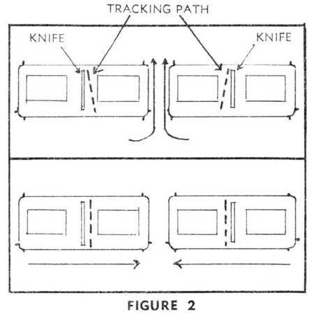
- 8. Run horizontal movement all the way back and start forward movement, checking visually through the optics to see that the alignment frame follows a path parallel to the cutting edge of the blade for at least half the width of the tape guide. If it does, the tracking is correct. However, if it is found that when the optics are moved forward, the edge of the shear blade moves to the right or left of the alignment frame, then the jackscrews found at the front and back of the baseplate may be employed to rotate the body of the splicer to bring the cutting edge of the shear blade into a tracking line with the alignment frame. (Fig. 2). Repeat the above procedure until a parallel tracking-line is reached.
- 9. Now that the parallel tracking line is reached, it may be found that the cutting edge of the blade still is either to the right or left of the alignment frame. This may be corrected by the use of the jackscrews located in the right and left ends of the baseplate. For example, if the cutting edge of the blade appears to the left of the alignment frame, loosen the right jack-screw and tighten the left, thus moving the splicer body to the right. This procedure should be followed until the cutting edge of the shear blade has reached the true tracking center of the alignment frame. (Fig. 2)
CAUTION: Check all jackscrews to see if they are tight while observing through the microscope. The operator should check carefully the first half-dozen splices made after a major alignment to see that there is no shift in the adjustment.
.
Recommended Procedure for Splicing TV Magnetic Tape
Recommended Procedure for Splicing TV Magnetic Tape
.
- 1. Pull saddlebar all the way forward and lock in position using both horizontal and vertical locks.
- 2. Develop portion of tape where splice is to be made.
- 3. Select the right-hand piece of tape to be spliced and place in right-hand tape guide, allowing the loose end of the tape to pass beyond the cutting edge of the shear for at least V2 inch.
- 4. Close and lock both left and right tape hold-down doors.
- 5. Swing light into working position. Note that the bottom of the light housing has a neoprene pad. This pad should ride about 3 mils above the surface of the tape in the tape guide. This clearance will allow the tape to be moved under the light housing pressure foot to obtain proper alignment. This clearance is obtained by slightly bending the hinge arms holding the light body either up or down as needed. Note also that a slight finger pressure on the top of the light housing will cause the neoprene pad to contact the tape and hold it securely in position while the cut is being-made. This pressure foot is necessary to hold in place the wild end of the tape while the cut is being made.
- 6. Focus optics to obtain a clear view of edit pulse.
.
.
- 7. Adjust tape to right or left by means of tape advance knobs to align the edit pulse with the alignment frame. (Fig. 3.)
- 8. When proper alignment of the tape has been achieved, finger pressure should be applied to the light housing causing the tape to be held firmly against the bottom blade of the shear. This pressure should not be relaxed until after the cut has been completed. Check visually to see that this motion has not disturbed the alignment of the tape.
- 9. Roll the right-hand tape advance knob clockwise. This motion will stretch the tape out flat and remove any buckles that may occur in the wild end of the tape.
- 10. Lock right-hand tape by tightening right-hand tape lock knob.
- 11. Swing shear blade into position with the right hand.
- 12. Cut tape by striking with the right index finger the slanted knob on top of the shear blade. This motion should force the cutting edges of the shear together as well as down to make the cut. The knob should be struck with the right index finger with sufficient force that the entire cut can be made at one time.
.
- 13. Finger pressure on light housing may be released.
- 14. Swing light to "rest" position.
- 15. Open left tape hold-down door and remove short: scrap of tape.
- 16. Develop portion of tape to be spliced in.
- 17. Insert tape in left tape guide.
- 18. Lower and lock left tape hold-down door.
- 19. Swing light back into working position.
- 20. Check through optics for position of edit pulse.
- 21. Align tape by using left tape advance knob.
- 22. Lock tape securely in tape guide by use of left tape lock.
- 23. Apply finger pressure to light housing.
- 24. Check through optics to see that tape alignment has not changed.
- 25. Swing shear blade from vertical position and make cut. Return blade to vertical position.
- 26. Release pressure on light housing and swing light back to "rest" position. (Light may be turned off now.)
- 27. With right thumb, depress knurled knob on splicing tape hold-down mechanism thus causing tape fingers to be raised.
- 28. With left hand, grasp short end of splicing tape protruding from splicing tape magazine and gently pull out vertically approximately 3 or 3% inches of tape.
- 29. Now place this tape on top of saddlebar trimming anvil and allow tape hold-down fingers to return to normal position thus holding the tape firmly and smoothly against the anvil. CAUTION: It is recommended that M" splicing tape be used with this machine. If y2" tape is used, wrinkles may occur in the splicing tape. The operator will find that with a slight amount of practice and by the manipulation of the splicing tape that these wrinkles can be eliminated without loss of time. Extreme care should be taken not to overstretch the splicing tape in this operation because it will pucker the magnetic tape after the splice is completed.
- 30. Rotate tape lift knob 90 degrees in either direction. This will cause the ends of the magnetic tape to be raised clear of the saddlebar.
- 31. Unlock saddlebar and push to the extreme rear position and relock, thus carrying the splicing tape under the raised ends of the magnetic tape.
- 32. With the left hand, slowly bring the tape lift knob back to its original position allowing the magnetic tape to settle on the pressure-sensitive splicing tape. Note that one side of the magnetic tape will approach and touch the splicing tape while the other side is still held free. Continue the operation until both sides of the magnetic tape fall into place.
- 33. Using the roller end of the trimming knife, the splice should be rolled gently but firmly to assure a uniform bond in the splice. If wild ends of tape are encountered, it may be advisable to use a cotton swab to help position the tape before rolling.
- 34. Now place the trimming block in the tape guide over the splice and use the machined edges as a guide for trimming off the surplus ends of the splicing tape with the trimming knife.
- 35. Remove trimming block and store knife in the holder.
- 36. Release both tape lock knobs.
- 37. Press both red door lock release buttons, raise doors to open position and remove tape.
.
OPERATIONAL ADVICE
Elimination of backlash or slack in the horizontal rack and pinion may be accomplished by first loosening the set screw found on the bottom right-hand side of the horizontal ways at a point just beneath the pinion shaft. Then rotate the eccentric bushing that forms the bearing for the pinion shaft. When proper adjustment is obtained, re-tighten the set screw. This adjustment may be made without dismantling any part of the splicer.
While making a splice, the operator may find a slight edge misalignment between the right and left hand tapes. This is caused by the tape manufacturer's tolerance which is 2" + .0, - .005".
However, it has been found that the high tolerance may be as much as 2" + .001" and the low tolerance 2" - .005". This gives a .006" spread in the width of the tape. The tape guide has been engineered to accomodate the highest tolerance and when the low tolerance tape is used, some tape slop or edge misalignment may be the result. This situation is common and varies from time to time. It may be corrected according to the best judgment of the operator in splitting the difference.
.
For the following reasons it is strongly recommended that at no time should anyone hold the eyepiece of the microscope in his hand to steady himself while using this machine:
Since the graduated scale is in the eyepiece of the microscope, its movement can be compared to that of the pendulum of a clock which moves only slightly at the top and swings in a much larger arc at the bottom.
Therefore, a 1/2 thousandths pressure on the eyepiece may show up as a 5 thousandths variation at the cutting line.
For those technicans wishing to make high quality splices, it will be found that a flat or dead tape will make the best splices. To accomplish this, we have found that proper care of tapes in storage is an absolute must. A few wraps of old tape around the reels will secure the end to be spliced, keeping it flat and dead. If a portion is cut from a reel and the above procedure is not followed, the severed end being allowed to fly about loosely, it will curl badly becoming live and very difficult to splice.
Although the splicing procedure may seem long at first, the operator will find that after a few days' practice, the development of the tape will consume more time than the actual splice.
S & S MANUFACTURING COMPANY ALTA LOMA, CALIFORNIA

